A shotgunning look into my random thought patterns, turning up surprisingly non-random, non-trivial connects on several hoopy wavelength. Your Mileage May Vary.
While I wait for #3 to bug me about her radio again, I'm working on my 10DE7 project.
Here's the skinny:
I took some parts that look like this:
and turned them into this:
and in the processed learned something about phasing.
Some project notes,
I did make the connection between taps 9 and 7 permanent, that is, soldered the wire in place. I made a short jumper with spades so I could experiment with places to put them on the taps. The first time, I soldered a jumper wire between pins 8 and 9, and didn't get the results I wanted. I thought for a minute that I had a bad transformer. I learned a couple of things in the process.
1. Autoranging digital VOMs can mess with your head. I kept getting jumpy measurements in the milivolt range, and it kept making me nervous. Verifying some readings with an analog meter really helped me settle down.
2. When dealing with AC transformers phasing matters. I should have realized from the schematic of the taps that the phasing a the bottom of one set of secondary taps would be out of phase with the top of the next set, but it took a little experimenting to figure that out.
3. When dealing with an unknown quantity, don't solder things down. I know better, but sometimes I don't do better.
4. Alligator clips for VOMs have their place.
I got to bed pretty late last night, so probably no shacktime tonight.
I have to think some more about plate voltages anyway.
I've decided to call my One Tube MOPA project "Operation Rock Garden." Because it is another project that involves a crystal controlled oscillator, I figured, why the heck not?
Phase one deals with power supplies. Not supply in this case, but supplies. There are three distinct voltages for this project, 2 different DC B+ voltages, and an AC filament voltage. Each one needs to be able to handle a certain amount of current as well. bBcause of this, I'll probably need a few solid state parts, like diodes and voltage regulators, for creating a rectifier circuit, or voltage doubler.
Step 1 of this phase is to light the filaments. To do this I need a circuit that can supply 9.7V at 600 milliamps. The easiest way to get there is to take the massive milsurp filament supply voltage I have, and series up the proper combination of taps to get as close to 9.7 as possible.
It came from a homebrew power supply for a Heathkit SB-102, and other than that, I don't know much about it, but I figure if I connect tap 8 to tap 9, and take my voltage from tap 7 and tap 11, I should have somewhere in the neighborhood of 9.45 Vrms, maybe a little more, because this primary is listed at 117 Vrms, and I'm around 120 consistently here.
Backside, showing taps.
I don't see this as an optimal solution, but it can handle the current, and the voltage should stay reasonably under the max. The supply has this lug sticking out of it.
The lug is behind taps 5 and 3. I think it's there so the core can be grounded, but I'm not sure the core needs to be grounded in the application I'm using it.
I will take advise in this matter.
Here's the plan for tonight when I get home from work:
1. Hook up the Transformer, ground (or not) the lug.
2. Construct tube base breadboard.
3. Go to bed. Light the sucker when I'm sure I have at least 9.4 Vrms, and after I've rested.
I'll be listening to 3579 KC while building, and the NoGA Twin Tube 80 will be standing by...
***EDIT*** General concensus is that the lug can be grounded with no ill effects, and the filaments should be ok at that voltage.
We'll see if I can get 'er done tonight!
******
I'm building a single tube MOPA. Yes, the same one I seem to almost build every year. :-)
This year, however, I have a plan! When you have a plan, you can win!
Sometimes.
The tube is a 10DE7, a higher heater voltage tube version of the 6DE7.
The circuit is a Crystal controlled Colpitts Oscillator. The only reason I'm doing this as a Xtal Colpitts is because I want my first foray into the world of tube design to be easy. I've built somebody else's tube Colpitts (The NoGA Twin Tube 80), so I figure that this will be a matter of scaling the design to the tube. Next I'll try a PTO Hartley. I've got the brass screw and nylon tube to wind a coil on for that!
I will handle this project in three phases:
1. design power supply. This tube has an interesting heater voltage requirement, so I have to solve that lil problem first. Also, need something that will give me around 300vdc for B+. I'm thinking voltage doubling circuit at first, just to see if I can do it. I'd use the same back to back radioshack 12.3v transformers to isolate the AC and then double the result. that should get me around 330v. I can drop voltage with a resistor if necessary. I want to QRV, not optimize right now.
2. Design the Oscillator and make it oscillate. I want to design the circuit in such a fashion that the compenents are accesable, but not dangerous. I'll socket the crystal somehow, and make sure all B+ voltages stay tucked away, shielded from wandering and little fingers. I want the board layout to be identical to the schematic layout, so I can understand how things are working, and I can tinker with values at will.
3. Design and build the final stage, including a way to remotely switch between receive and transmit. If I've done my calculating correctly, I should be able to get 3-4 watts out. High hopes? Yes. But we will do it as we are able.
Once QRV with this radio, I'll work on a receiver, probably something DC, and involving that Hartley oscillator. It will glow in the dark too, and will be used primarily with this transmitter.
Recently, on the "Glowbugs" google group, there was a discussion about whether a pill or vitamin bottle was suitable for use as a coil form for a tank curcuit, or other more general RF use (loading coil form, etc).
According to that fine bunch of OMs and YLs, the test is temperature after being microwaved for a bit. Here's how the test works:
1. Take a microwave safe dish, and put a cup of water in it. Make sure dish is shaped so that both dish and test bottle can fit in the microwave oven without one being on top of the other.
2. Clean and dry the container you want to test. I tested a bottle that held fiber, that's what's in the picture. Trickiest thing about the prep work on this baby is that you want to make sure all the metal from the freshness seal is removed from the rim.
3. Place both the test bottle and the cup of water in the microwave. Take note of the temperature of each, "room temperature" is as precise as this measurement needs to be.
4. Nuke it for a minute. (see below for further advice)
5. Compare temperatures: the test bottle should still be at room temperature, and the water should be noticably hotter (scalding hot on some microwaves, so be aware!)
Them what was tested.
Above is my test bottle, a repurposed fiber containment vessel. Errr, it's not mine man... I'm to young to take a fiber supplement! (maybe...)
K5KVH had mentioned the RF microwave test, and this is what hed had to say way back in 2011 on the Glowbugs list:
PVC is easy to verify if it has additives to increase loss. You can
check your PVC easily with the microwave test. Put a sample of the pvc
on a paper towel in the microwave oven. Put a cup of water in there
next to it. (no metal trim on cup, plain china).
Set the microwave to 3 or 4 minutes. When you see the water is boiling,
stop the oven. Carefully test the pvc with a wet finger tip, to see if
it got warm, ie warmer than the hot air around the cup.
If not, it is good for HF for sure. This is based on a formula for
dielectric loss that shows such loss is directly proportional to
frequency, the higher the test frequency, the higher the loss would be
for a given material. Thus, no heating at microwaves means it is
a good insulator at HF.
Ok, I will buy that.
My test results indicate that this material is good for winding tank circuits, or whatever, at HF frequencies.
It is made of "Recycle Material Number 2", ie High Density Polyethylene (HDPE).
I recently acquired some more tubes, so I'm probably going to be using this soon.
Getting the power supply working, putting out good, well filtered voltage was relatively easy. The hard work was getting the radio itself QRV once again.
That's right, more problems.
Seeing that I was trying something crazy, like switching tubes, I decided that I would revert to the original two tubes, in their original sockets. Why tempt the smoke? It needed to stay in the caps this time, or money would be spent!
I put the two tubes in, confident in the knowledge that I have made QSOs with these tubes, tuned the Swan 100-MX to 3579ish, tuned the antenna on that frequency, switched antenna outlets, keyed down, and heard noise! Victory? Not quite.
So I tried peaking the tank cap, no dice, then went investigating the tube sockets themselves again because I stopped getting any signal out when I jiggled the connection. I didn't notice anything immediately obvious, but Warmed some joints anyway, and made sure nothing was shorting anything out.
Then....
I packed up shop for the night, scowling at my fortunes.
No power, no nothing, just time for bed.
Suddenly, I had an idea!
What if one of the tubes was bad? Like the one that was still on the chassis when I smoked the radio the first time? Couldn't hurt to try right?
Sho' nuff, soon as I switched tubes and gave it a minute to warm up, bam! power out. Then I went to bed.
Time for the Finishing touches
I decided to button up the power supply. I clipped the primary to secondary connection to shorten the wires. The plan here was to mount the capacitors and surge resistor in the middle and the rectifier more or less on top of the secondary transformer.
More or less that's how it went.
Getting that bugger in there was tough! I had to cajole, caress, tweak and twitch over the course of two nites, but sure enough, it happened, and I was able to get that sucker in there!
Now it's time for a QSO!
That corresponds to ONE BLAZING WATT of RF on a dummy load.
On to the next project!
73,
DE KG4GVL TT-80 QRT
Thank you all for reading!
ps,
I will occasionally post followup articles to this series, and will keep a list of all the states I've worked and confirmed. My goal for this rig will be WAS or something. Look for me round about 3579KHz, in between all the digi stuff...
Ok, so things went well in the wee hours of the morning for the power supply. I'll let the videos speak for themselves:
I had to turn the camera off to capture the results because I couldn't find a safe way to hold my camera and take the measurement. Here's the after video:
The power supply is pretty much ready to run at this point. All that is left is packaging and hooking up the radio, There's just one last check to make, the one for ZAP!
The rest of the night was pretty interesting and I have some more testing to run before I'll be ready to post.
So Here's what I have been able to discover:
I'm still not 100% certain why the unit failed the first time. Initially I suspected the power supply, but I'm reinvestigating, I discovered another loose solder connection on one of the tube sockets. I'm not sure that's what did it, but I'm always suspicious of any changes I made. I changed tubes, the supply blew up. Thems the facts. Whether changing the tube caused a supply malfunction remains to be seen.
You can notice from the pic that I changed out the crystal holder part of the circuit. I did this to keep the metal case of the crystal WELL away from the supply voltage terminal, and because it looks better put together up and off of things as opposed to flopping around all dangly like. The bad news is my thumb is sore today because I think I poked it with a wire. If things don't improve soon, may have to go see the Dr about lockjaw! Heh!
how you 'spain that one to the XYL?
The second time the supply failed, I am 100% certain was because I used a severely underrated rectifier diode. I used a 1N4001 blindly following a misprint in the schematic I was using, instead of a 1N4004. So I'm beefing up to a 1N4005 just to make sure, and that's only IF I can't find any 1N4007's laying around the junque box. Next I will isolate the 150 B+ part of the circuit from the line, and instead of using one diode, I will go ahead and use four, building a full wave bridge rectifier. This is because I got diodes, and math is on my side...
From an awesome mess
Comes a beautiful circuit
Arise O Phoenix!
OK:
so you take a half wave rectifier like W3IRZ(sk) first designed into this rig, and you take the caps he had for smoothing, do some funny math, and using the max transformer rating of 1 amp. I'm not expecting to actually draw more than about .05 amp here, and yes, I know about derating the transformer current rating in a bridge rectifier, the actual rating is 1.2 Amp. Radio Shack sells a 3 Amp transformer too, it is part number 273-1511 you can ship it to my address from QRZ.com or hit the donate button in the top right hand corner of this webpage :)
anyway,
you do the math found at MIT: and discover that there is 24.1 Volts of ripple voltage when the load draws 1 Amp.
Now this is worst case scenario mind you, but still. at 50mA which is a lot closer to the actual current draw, it will be a lot less, like 1.205 volts ripple, which is less than 1% of peak voltage (150VDC). An acceptable number, but since the 470 microfarad caps needed to produce this performance are now BBQ in the trashcan, it's time for plan B.
I have some caps suitable for filtering, but not the exact values as before. I needed a way to lower the required amount of smoothing needed to get a usable DC voltage. I decided to build a bridge rectifier, and use a couple of caps left over from the earlier efforts. Using two 220 microfarad capacitors, I actually drop my ripple voltage a little bit, to like .95 volts at 50mA. I can handle that!
Now you can buy a bridge rectifier at the local shack, but this is an exercise in understanding, and I don't have any 1 Amp, 120Vrms AC bridge rectifiers in the Junque box. I do have 4 1N4005 diodes though, and knowledge, and a community of assorted skalawags, errrr, electrically inclined persons who can help me out.
This is the bridge, as I have constructed it. The alligator grippers are holding it at the position where I hook in the AC, one side to top, one side to bottom.
The bridge will be hooked the (originally primary) secondary of a 12.6VAC to 120VAC transformer.
Here's a closeup, showing the AC wires hooked into the circuit. I've intentionally left the 'ears' on the soldered circuit leads so I can do some testing later. You can see that the bands indicating the cathode of the diode are running from left to right. As it is layed out, the rectified positive voltage will be on the right, and the negative side is the left.
This is an overhead shot of the circuit so far, laid out on a potential housing mount. The pic is upside down from the way that I took it, but whatever.
you see that I have two identical transformers, they are Radio Shack "120-12.6VAC 1.2 Amp" available at most stores. I have rolled up and taped off the center tap of the transformer, because I don't plan on using it. The two outer leads have been tied together. I will take my 12 VAC filament voltage from this point. Hot and neutral wires will be hooked up to the primary transformer on the left, and the diode bridge is hooked up to the secondary transformer on the right. If all goes well, and I haven't done anything stupid, we will have pulsed DC ready for smoothing at the secondary end.
Here's a video showing how everything is currently laid out:
I won't be hooking AC up to it until I've got the unit planned out and tightened up a lil bit, namely I will be solving space issues, hooking up a switch and fuse set up, and hooking it up the way I will have it inside the box.
So what do you guys think?
Go or No Go?
I decided to open the power supply up, and clean up some circuitry. I wanted to make sure that things stayed put once I was ready to QRV. Here's how things looked before getting them all put together.
Innards of the power supply. You will see in the final pic that I replaced the B+ wire, the red and black wire in this picture
and here's the transmitter:
I secured the top to the the lid using some ultra heavy duty fastener called dual lock. I wanted a rock solid mount, and I think I got it!
I have two other plans for the transmitter that I haven't decided if I'm going to do yet or not. First, I'm thinking of replacing the clips for the crystal. I'm not really satisfied with how they connect but they are protected. Second, I'm thinking of breaking the rig down, and redoing the chassis all together. The lil' Altoids tin it's on now is showing its ten years of age.
In this pic you can see the transformer, two filter caps, ground connection, and B+ line out. Everything is ready to be buttoned up and fed AC! The caps are mounted to the aluminium plate using mounting tape, and actually rest upside down inside the Power supply. I actually bought a 50 Ohm 10 watt resistor to go between the caps, but decided that the 45 ohm 5 watt would work better because of size. Radio Shack doesn't carry a 45 Ohm power resistor in the store, they carry a 0.47 :/
if you look closely at the power cord, it has a piece of heavy gauge magnet wire wrapped around it, this is to prevent me from accidentally pulling the cord out of the power supply, placing stress on the solder connections, and generally increasing the potential for fail.
Now for a demonstration of the awesome power of hollow state:
My theory on increase power output is that the powerbuss solder connections are better now, and tubes are awesome.
seriously on the powerbuss connection though.
Originally, in the interest of using things over and making due, I had hooked up connections with some spare wire I had laying around that at one point in time was part of a microwave. I noticed when I was hooking things up that this wire was silverish and didn't take solder well. As I remember there was no solder for power buss lines in the microwave, it used crimped terminal connections. hmmmm, probably is made from something from the lowest bidder. Fortunately, I also had some real buss wire laying around, so I replace unknown material with copper.
More copper means less power wasted heating a wire.
Here's how everything looks set up and ready to play:
no QSO yet. Will announce on twitter, QRP-L, SKCC facebook group, and other places when I get QRV.
Now that I am reasonably sure of my polarity, and I'm done cussin' the feller who put this plug together, it's time to go over the transmitter itself, and see if there's any improvement to be made. Heh. My radio uses 2 6AQ5A's in parallel. The filament takes 6 volts, and are wired in series. Right off the bat I saw that I had I had the filaments wired in parallel. This was from a time when the only transformer I could find was a 120v AC to 6v AC. I certainly corrected that lil' problem. It also explained why the sucker glowed a lil' more than I expected the first time I lit it up. 12v on a 6v filament will do that. I'm glad I didn't blow the tubes! I also cleaned up some wire and leads underneath, and made sure my point to point all went to the right places. In the process, I discovered a cold solder joint, and found a better way to route some parts.
The Kind of Ugly that's a Pretty all of it's Own
It's not necessarily my best work, but hey, it will do!
And yep, that's three 33pf NP0 capacitors wired in parallel.
Time to do some testing.
first, go see Dave Benson's website, Small Wonder Labs, and order a rockmite :) also, check out his documentation section. Download a manual for the SW-40+ transceiver, and look in the testing section. In that section is a circuit you can make pretty easily, and use it to measure the power your radio is putting out. I built mine on some radio
Circuit, dummy load, and babyfood jar.
Prototyping board, specifically so that things would stay together. I connected the orange and yellow wire across the dummy load, and made sure that I hooked the yellow wire to the side that goes to the pin, and the orange wire to the side that goes to the ground side of the plug. At the measuring end of the plug are two posts made from surplus resistor leads, I hook my Digital VOM to them using probe hooks. The set up is hands free once you hook the probes onto the posts, and turn on the VOM.
Here's a little video about what I discovered when I measured the voltage across the dummy load:
Ok, so, according to theory, the voltage measured here is Peak-to-Peak voltage.
Knowing that, tell me how much power is getting to the dummy load.
Show your work!
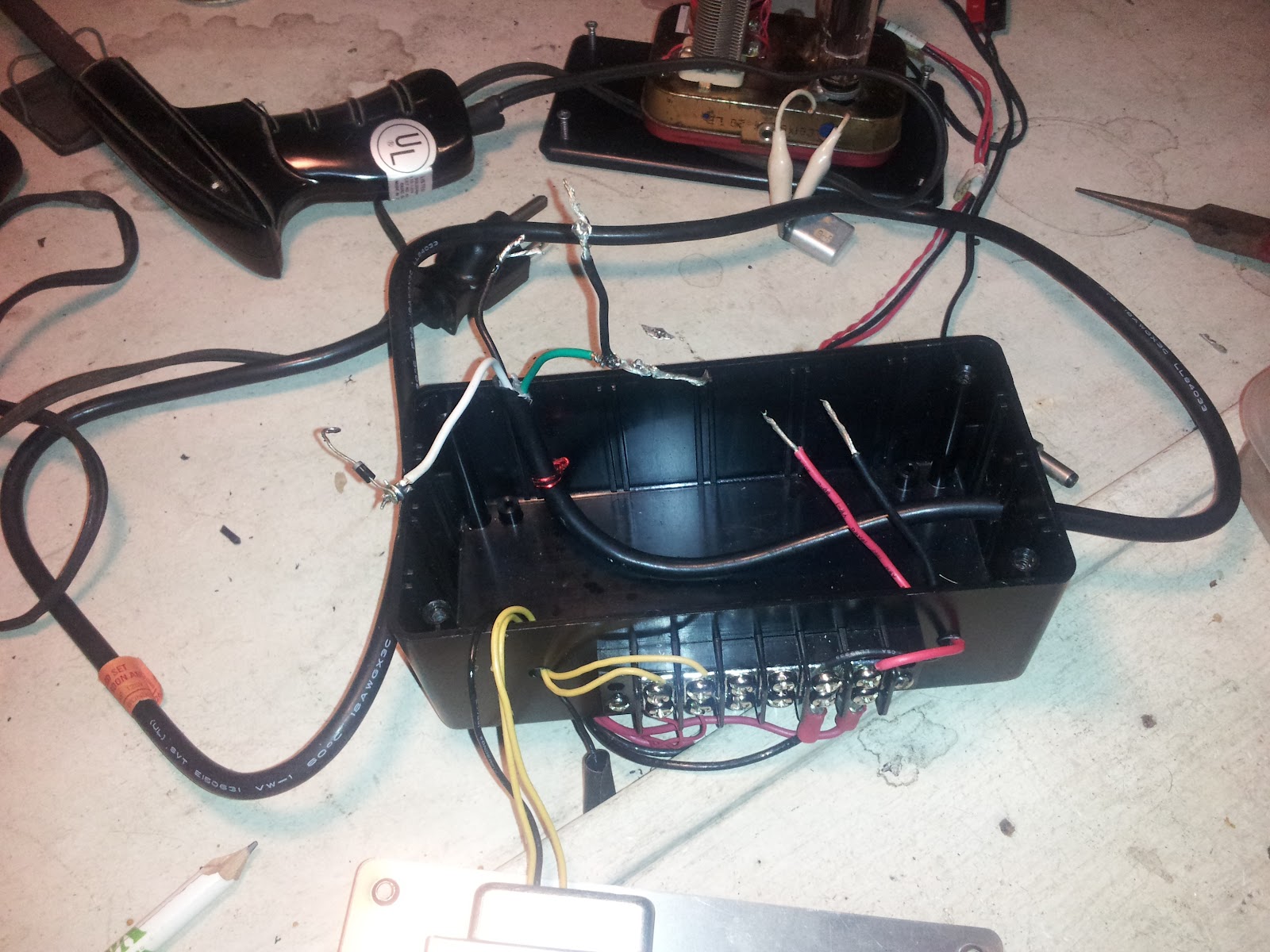
I didn't want to button my power supply up before figuring out why the hot wire was white. Basically, I wanted to make sure this radio could work anywhere, and having a hot white wire was troubling. Like David suggested in his comment, I suspected the outlet, and then the wiring in the Mains box. Time to flip breakers and do some inspecting!
First, I flipped the breaker to the shack, and trundled back into it, hoping to find a black wire where a white wire should be. The Shack in the Back was built before we moved here, and is 'unfinished'. The guy who owned the place two owners ago built it with scraps left over from some of his contracting jobs I think. When I unscrewed the socket from the recepticle, everything looked, well, fine. I was impressed with the craftsmanship of the socket to tell you the truth, connections were tight, and in the right place. Time to check the mains box, but I knew it was going to look fine there too. It did.
Back to the thinking bucket.
Yon Thinking Bucket
I juiced the shack back up, grabbed my VOM, and began doing things my mother told me not to do, namely sticking metal things in electrical outlets. By metal things, I mean VOM probes. I always feel weird sticking things into electrical outlets, makes me make sure I do so with fear, and caution. That's not a bad thing, I suppose.
First, I checked the socket for power, Hot wire to neutral, and I got 120v AC. Good!
Then I checked for what should be the neutral wire to ground, and got no AC voltage, Good!
for the kicker, I checked what should be the Hot wire to ground, and got 120v AC, Good!
So the socket is good! Should have done that first instead of assuming it wasn't... hmmm.
Next test, the power supply strip I plug into the socket. Maybe there's something miswired there,
Just checked Hotside to ground, 120v AC. Good!
So the power supply is not the issue.
must be the power cord.
The Cord- Not Polarized
notice that in the picture of the plug end, the plug is not polarized. This plug and wire was salvaged from some piece of computer equipment, and at one point in time had a female chassis mount plug on it, the kind that looks like this:
Female Chassis Mount
On a polarized plug, the narrow slot/prong is hot, the wide slot/prong is neutral and the round prong is ground, my non polarized plug fits in the socket the way a polarized one would, but, was it wired like a polarized socket? Just where did the white wire go?
I made sure the plug was unplugged, clipped the cord out of the power supply, and I decided to idiot check the green wire first, green for ground right? Switching my VOM to measure resistance, I continuity checked the green wire to the round prong, and it was Good! Then I checked between the other two wires, and no other wire lead to the round prong, Green is good!
I then oriented the plug like I was about to plug it in.
Right is hot, left is Neutral...
As this picture shows, the prong on the right, goes to the hot side of the socket. That's the one I want to check.
First I check the black wire, no continuity.
Then I check the green wire, no continuity.
Finally, I confirm that the right prong, the prong that normally connects to the hot side of the plug is connected to the white wire.
The white wire is hot because it goes to the hot side of the socket.
Heh.
I have no idea why this cord is made this way.
I just know that I can safely button up the power supply knowing It's the Cord, not my shack!
This is part 1 of a series, a complete list articles in this series is available under "Ham Radio Master links" on the sidebar.
Recently I've been wanting to clear various projests out of my project queue. Some of them are things I've been working on, and needed specialized parts to complete it. Others were not working because of technical issues. Some are because I'm afraid of drilling holes into some things and potentially ruining them :-) This last week I've been working on a radio that has vexed me for for ten literal years. The radio is the NoGA Twin Tube 80 schematics and instructions available at that link. I built it as it appeared in the NoGA Compendium available here. The kit itself is no longer avaible, but the parts to build it are out there. Mike Branca W3IRZ (sk) helped me get the kit working when I was having issues with it at my house. My goal was to put it on the air for the NoGA CW net on Tuesday nites. Well, Mike gave me a lot of great advice about building radios on that trip to his shack, and at the end of the day I had a working radio. On the drive home, something affected the æther stored in the radio, and while after plugging the radio in, I got no smoke out, neither did I get any RF! Alas ! Every trick I tried played out, and I set the little tube transmitter aside for other projects. Somehow, I knew the problem was in the power supply. I suspected the large value capacitors in the rectifier circuit.
Fast forward to the present.
Every time I would look at this radio I would get sad. Sad for the loss of a friend (W3IRZ sk in 2003), and sad that I couldn't seem able to figure this thing out. I decided it was worth a try. Time to stop being sad, and get back to slingin' dits and servin' dahs.
Since I've always suspected the powersupply in this radio, I decided to just hammer away at the power supply until it was working. The way this particular rig works is that you have a 12 v ac line for the tube filaments, a 150 v dc line for the plate, and a ground that you ground through the plug. I got out my caps, diodes, resistor, plug, and began the project for the third time. After soldering everthing together, making sure to follow instructions, I took the leap and plugged it in. No smoke! I tested the 12v ac circuit. I got 13v, that's ok, the transformer output is actually rated at 12.6v ac, so no big surprise. The 150v dc line, no dice.
Hmmmmm, this is where I left off ten years ago. I went to bed dejected and tired. I'd stayed up until 3:00am for nothing. I hadn't even learned anything yet. Course all that was going to change the next night.
I do my best to junk out old stuff so I can have strange parts when I need them, you can't buy 220 microfarad 250volt rated capacitors at radio shack. You have to go online and look them up on Mouser or Digi-Key. Fortunately, one of my recent junking exercises produced the caps I needed. This is recycling! The next night I replaced the caps and diode (just in case) double checked my wiring, plugged it in, and nothing! Still no B+ voltage. Dejected I tuned around the band hoping to find something interesting. I began thinking of what the issue could be and applied a little problem solving.
Grabbing the VOM, I hooked the ground wire up to the black probe and began poking things with the red. Positive terminal of 470 micro farad cap, nothing, positive terminal at 220 microfarad cap, nothing. Bottom side of 1N4001 diode, nothing. Top side of 1N4001 diode, I switch to AC because I'm connected to the ground and the black (hot) wire directly, nothing. Wait, whut?
Nothing?
I have 13v ac at the transformer, between the white (neutral) and black (hot) wire I have 120v ac, but between green and black I got nothing?
Then it clicked. The black wire wasn't hot, the white wire was! Two snips and a dab or two of solder later, and I have the white wire hooked up as if it were hot, apply juice, check voltages, and we are good to go:
How's that for live action?
It's also why every shack needs a 'chicken stick' of some sort. Link takes you to a qrz.com site all about stories of chicken sticks.
So, I have power at my supply, but It's coming from a funny wire. Before buttoning everything up, I needed to figure out Why the White Wire is Hot.
That's Chapter 2!