A shotgunning look into my random thought patterns, turning up surprisingly non-random, non-trivial connects on several hoopy wavelength. Your Mileage May Vary.
While I wait for #3 to bug me about her radio again, I'm working on my 10DE7 project.
Here's the skinny:
I took some parts that look like this:
and turned them into this:
and in the processed learned something about phasing.
Some project notes,
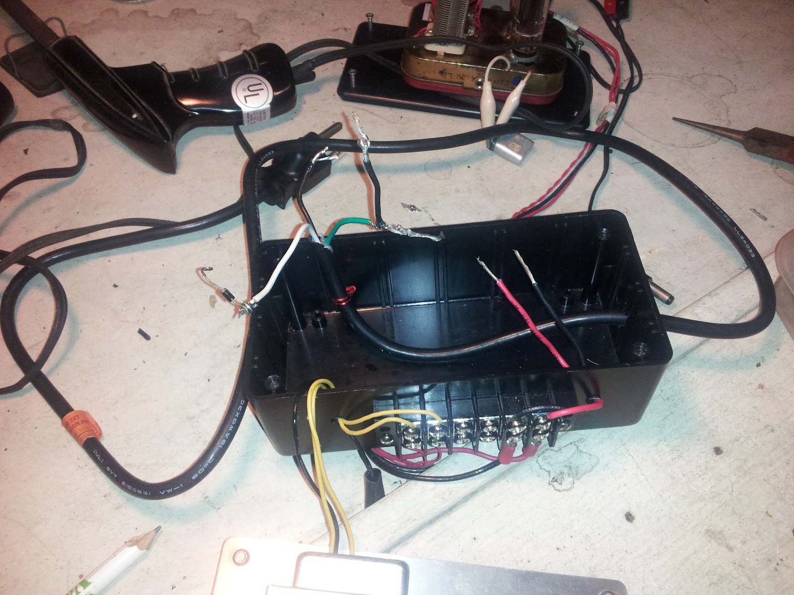
I did make the connection between taps 9 and 7 permanent, that is, soldered the wire in place. I made a short jumper with spades so I could experiment with places to put them on the taps. The first time, I soldered a jumper wire between pins 8 and 9, and didn't get the results I wanted. I thought for a minute that I had a bad transformer. I learned a couple of things in the process.
1. Autoranging digital VOMs can mess with your head. I kept getting jumpy measurements in the milivolt range, and it kept making me nervous. Verifying some readings with an analog meter really helped me settle down.
2. When dealing with AC transformers phasing matters. I should have realized from the schematic of the taps that the phasing a the bottom of one set of secondary taps would be out of phase with the top of the next set, but it took a little experimenting to figure that out.
3. When dealing with an unknown quantity, don't solder things down. I know better, but sometimes I don't do better.
4. Alligator clips for VOMs have their place.
I got to bed pretty late last night, so probably no shacktime tonight.
I have to think some more about plate voltages anyway.
I've decided to call my One Tube MOPA project "Operation Rock Garden." Because it is another project that involves a crystal controlled oscillator, I figured, why the heck not?
Phase one deals with power supplies. Not supply in this case, but supplies. There are three distinct voltages for this project, 2 different DC B+ voltages, and an AC filament voltage. Each one needs to be able to handle a certain amount of current as well. bBcause of this, I'll probably need a few solid state parts, like diodes and voltage regulators, for creating a rectifier circuit, or voltage doubler.
Step 1 of this phase is to light the filaments. To do this I need a circuit that can supply 9.7V at 600 milliamps. The easiest way to get there is to take the massive milsurp filament supply voltage I have, and series up the proper combination of taps to get as close to 9.7 as possible.
It came from a homebrew power supply for a Heathkit SB-102, and other than that, I don't know much about it, but I figure if I connect tap 8 to tap 9, and take my voltage from tap 7 and tap 11, I should have somewhere in the neighborhood of 9.45 Vrms, maybe a little more, because this primary is listed at 117 Vrms, and I'm around 120 consistently here.
Backside, showing taps.
I don't see this as an optimal solution, but it can handle the current, and the voltage should stay reasonably under the max. The supply has this lug sticking out of it.
The lug is behind taps 5 and 3. I think it's there so the core can be grounded, but I'm not sure the core needs to be grounded in the application I'm using it.
I will take advise in this matter.
Here's the plan for tonight when I get home from work:
1. Hook up the Transformer, ground (or not) the lug.
2. Construct tube base breadboard.
3. Go to bed. Light the sucker when I'm sure I have at least 9.4 Vrms, and after I've rested.
I'll be listening to 3579 KC while building, and the NoGA Twin Tube 80 will be standing by...
***EDIT*** General concensus is that the lug can be grounded with no ill effects, and the filaments should be ok at that voltage.
We'll see if I can get 'er done tonight!
******
I'm building a single tube MOPA. Yes, the same one I seem to almost build every year. :-)
This year, however, I have a plan! When you have a plan, you can win!
Sometimes.
The tube is a 10DE7, a higher heater voltage tube version of the 6DE7.
The circuit is a Crystal controlled Colpitts Oscillator. The only reason I'm doing this as a Xtal Colpitts is because I want my first foray into the world of tube design to be easy. I've built somebody else's tube Colpitts (The NoGA Twin Tube 80), so I figure that this will be a matter of scaling the design to the tube. Next I'll try a PTO Hartley. I've got the brass screw and nylon tube to wind a coil on for that!
I will handle this project in three phases:
1. design power supply. This tube has an interesting heater voltage requirement, so I have to solve that lil problem first. Also, need something that will give me around 300vdc for B+. I'm thinking voltage doubling circuit at first, just to see if I can do it. I'd use the same back to back radioshack 12.3v transformers to isolate the AC and then double the result. that should get me around 330v. I can drop voltage with a resistor if necessary. I want to QRV, not optimize right now.
2. Design the Oscillator and make it oscillate. I want to design the circuit in such a fashion that the compenents are accesable, but not dangerous. I'll socket the crystal somehow, and make sure all B+ voltages stay tucked away, shielded from wandering and little fingers. I want the board layout to be identical to the schematic layout, so I can understand how things are working, and I can tinker with values at will.
3. Design and build the final stage, including a way to remotely switch between receive and transmit. If I've done my calculating correctly, I should be able to get 3-4 watts out. High hopes? Yes. But we will do it as we are able.
Once QRV with this radio, I'll work on a receiver, probably something DC, and involving that Hartley oscillator. It will glow in the dark too, and will be used primarily with this transmitter.
I'm in the process of designing and building my own MOPA using a 10DE7 vacuum tube. I want to use one tube for both the Master Oscillator and Power Amplifier. It's been a great learning experience so far, I go to sleep every night with Colpitts Oscillators dancing in my head. One of the tools I've used when building a radio has been a Peak to peak RF voltage reader. This circuit is described in Dave Benson's instructions for his SW+ series of radios. Better go download the manuals! Dave's closing shop in favor of retirement, and he won't leave the site up forever. When I built the circuit, I decided to put it on a board, and let it dangle off of my dummy load. That got annoying though, and there was always the problem of what to do with the dummy load when I was done measuring power. Evenually I just ripped the circuitboard off of the dummy load. Then I had a thought.
Since the circuit uses components that are QRP level, I decided to go with a QRPish dummyload. A long time ago I located some 2 watt 200 Ohm resistors. I used them to make a dummy load that would handle 8 watts. The circuit board once upon a time dangled from the dummyload like some sort of absurd dangily earring. It just makes more sense to put the dummy load on the circuitboard. This is the result shortly before hookup:
Dummyload Added!
To insure that all my resistances were correct, and I could sanely measure voltages, I did a quickhookup to check out voltages, etc, before putting in an Altoids tin.
Ready To Test!
Once the little job was ready to permanently affix to the inside of an altoids tin, I located some two sided sticky stuff I had laying around, and attacted to the bottom of the altoids tin. I may have said "Oh Good Grief" or something like that when I realized that the board was a lil' bit crooked in relation to the bottom of the box. After hooking up a BNC connector, and attaching the wire to my test point, my RF voltage meter was ready to use.
Ready to Use!
I plan on using this to test my designed Colpitts oscillator, but until then, the glowbug I have now will have to do. The first time I measured the voltage things seemed a little low.
This seems low.
That measures out to 0.9216 watts. ((Vp-p * sqrt(2)/4)^2 / 50) And then I got to thinking. I remembered that the last time I checked the RF output on this lil' tube radio was without my NoGAwatt attached! I pretty much just used just the dummy load dangling off the back of the radio. That was one of the reasons why I moved my dummyload onto the circuit board.
I took the NoGAWatt out of the equation and this is what I got:
Much Better Now!
For a whopping total of 1.092 watts! Just to make sure there wasn't anything crazy happening with thee coax I was using, I used both pieces of coax I used for the first test, and substituted a BNC female to female barrel coupler to see if adding that particular section of coax would alter the power out at all:
Not Much!
That confirmed my suspicion, The NoGAwatt was consuming power. Not surprising, since something has to make the needle move to indicate forward and reflected power. I bet I could calculate the maximum amount of power lost to the meter based on the full deflection reading of the needle...
ah, maybe later. Right now is time for operating!
One last internal shot.
I still have some prettying up to do on this lil-bit-o-kit, namely, I need to find some better way of hooking the RF measurement points up to make them accessable without being in the way, or easy to short out. Right now I'm just using the "situational awareness" method, and that doesn't always pan out.
Eventually, I hope to make this something that is publish worthy. We'll see how that works out.
Much of Amateur Radio relies on using, or reusing things in ways which the equipment designer didn't intend. I've seen rectifier diodes used as variable capacitors, small signal diodes used as voltage doublers, high speed switching transistors used as buffer amps, and oscillators. I've even used flourescent light bulbs to test for Radio Signals emminating from my antenna. That's where this piece of Vintage Junque comes into play:
Heathkit, OOOOHHHHHHH
I got this for free when visiting a fellow ham, and he said "It might work..." I plugged it in and PPPPBBBBXXXZZZZZZZZZZZZZZT! went some electrolytic capacitor in it.
Ok by me, it has tubes and sockets, and a power transformer inside! I decided to dismantle this stately relic from bygone days in between QSO's while hangin' out in "The Shack in the Back". If I can't bust the pile up, might as well bust up a pile of junk!
Once upon a time Heathkit was a company that "Made builders out of ordinary people" and I've got to admit, most of the time, I'm pretty ordinary. Looking inside the monitor, we see a plethora of old mil surplus parts. That is correct, one of the things that made Heathkit possible in the era of time in which it existed was the presence of a large and cheap supply of surplus parts.
Nothing like that exists today.
I suppose that's why Elecraft costs so much.
GUTS!
Inside this station monitor you find several interesting things, notice how big the carbon composition resistors are, and how they are %10 tolerance resistors. Don't find them in Radio shack these days! No sir! they have them fancy pants %5 parts. High tolerance that is.
Cleaned out some.
Cleaned out the chassis some in this pic, let's take a closer look at the sockets I removed:
Socket to me!
Once I'm done cleaning this thing out, it will be perferct to serve as a test bed for all sorts of MOPA's, VFO's, Regen RX's, or whatever I think to stick in it!
Let's just hope it survives the rain we will be getting over the next couple of days.
Been a while since I posted on the NoGA Twin Tube 80 (link opens the first article in the series, see Ham Radio Masterlinks for a list of all the articles), figured I'd post an update, and talk about some project ideas I have for this set up.
Not long after successfully using the transmitter, I ran into a difficulty. The next time I tried to use it, I powered the radio up, I got sparks when I keyed down! Hmmm, that's not right! I also was getting no power out.
I decided to give the rig a break for a lil' while, and focused my efforts elsewhere. Since I was going to be up, I took the transmitter back out, and began poking about.
2 months hadn't improved the situation, it still didn't work.
Power supply was good,
I suspected the transmitter had shorted something out when I tried to go poking about the last time I successfully used it, I wiggled wires, and mushed down parts. Still no dice.
I replaced the three 33pf capacitors and checked the 100microhenry inductor for continuity.
I then inspected the pins on the tube sockets, and sighed when I saw that pin 6 had a loose hookup wire.
hmmm, soldered that puppy down, made sure everything is bent to not short out, and closed the case back up. I think that the use of an Altoids tin in this situation is a mild gamble. It works decent enough, but there have been several times when I've come dangerously close to knocking something seriously out because the tin is somewhat flimsy when you begin poking holes in it.
I plugged the transmitter in, and things began to glow.
no Smoke, and no fires. That's a good sign.
Glow in the tube, antenna is a dummy load, DVM on, and keydown.
20V on the meter!
that's 1 watt folks.
we back in business!
The Thermionic Energy is Astounding!
These two glowing eyes
Voltage amplification
This is hollow state.
Of course, now I need to find someone to QSO with late at night on about 3582 KHz. The crystal is 3579.4 KHz, nominally, but it pulls a little higher in this circuit, I'm guessing that I need to add some capacitance somewhere to pull it back down. That gets me to my next point.
Back when I was building this thing, several suggestions for experiments were made to me, but it's not easy to swap parts out of this altoids tin. I've got a couple extra tubes that will work in this getup, and I'm thinking of building a breadboard that I can plug parts in and out of. I need some more tube bases first though.
The schematic is availble for view HERE. KL7H has done a great job of documenting this and Mike's 12 v regen project.
Any suggestions for substitutions?
Should I attempt to wire one tube as an oscillator and the other as an amplifier? (MOPA esque?)
Suggestions for boosting power?
73!
Good news, I made my first QSO with the Twin tube 80!
Bad news, won't be making another one any time soon!
Yay smoke!
In Chronological order, the good news first:
I made my first QSO with this rig!
Yep, it's true, actually made my first two QSO's, one with W1PID in New Hampshire, and one with AK4O down the road from me in Tampa. I got so excited, that I forgot to video the QSO w/ W1PID, even though that was my intention. Here is a vid from right after the QSO,
I felt pretty good about it!
About three hours before 9pm (local time, 0100 UTC), I announced that I would be QRV at 0100 UTC on the QRP-L reflector, the NoGA yahoo group, and other places. About 20 minutes before starting, I went out to the shack, turned on the RX rig, and plugged in the TT80, I noticed a lil' spark right as I plugged it in, looking back I think this was the beginning of the end of the capacitors in this iteration of the power supply. At the time, I didn't think anything about it because hey, tubes were glowin', and there was no smoke!
After getting some of the kids in bed, and tucked in for the night, it was radio operating time. I started calling CQ, and it seemed like almost immediately, I got a return, notably, from W1PID, click his call sign and read his adventures, they are well worth it! He takes his radios all over the place :) Considering my antenna on 80m is a W3EDP with the counterpoise unhooked (is just over 1/4 wave on 80m), and worked against my station ground, I'm glad to have worked anyone, but feel especially good that my signal made it all the way to New Hampshire!
I then took to calling CQ again. Avoiding static crashes, and other QRN, and the ever present Digi QRM, it wasn't easy, especially using the Swan as a receiver. It says "CW" on the mode selector switch, but this is a lie :) it's really the USB SSB filter working, so you hear 2.7KHz of bandwidth all at once. I've had some success using an active audio filter, but I've got a lot of work to do in the shack before I get that particular aspect of the problem solved. I have seen people homebrew CW filters to install in the Swan 100MX, but I don't know if I will yet or not.
About 20 minutes after the first QSO, I copied and replied to AK4O who lives about 36 miles from me (as the signal flies), and also got a nice email from him. I called CQ some more after that, for about an hour, without any luck.
Then, I unplugged the TT80, and tuned around some with the Swan, on 80 and 40, and decided to start trying different tubes (same type) in the sockets. you know what they say about not messin' with a good thing?
And Then:
EGADS!
Whatever went on in there, wasn't good.
hmmm,
since the first thing I did was change out a tube, I checked the tube base, and I didn't see any obvious shorts, so I began to suspect the capacitor. I remembered the extra beefy spark when I first plugged in the power supply, and I knew I had a suspect!
I found pieces of the rectifier diode, and cleaned up the box and filament transformer with simple green. That's some awesome cleaner. Then I decided to function check the filament transformer. It passed. I tested the resistance across the power surge resistor between the two capacitors: it failed. No continuity!
I then rewired up a new power supply using my last 470 microfarad 250v rated electrolytic, and a new 220 microfarad 250v electrolytic. I went to a 50ohm 10watt power surge resistor (it was as close as Radio Shack could get). Now I am ready to test things out before hooking the TT80 back up. I'm just looking for 150V dc power. Whelp, as soon as I plugged it in the 470 microfarad blew up again.
dang.
I'm throwing this cord out, grabbing another, and trying to scrounge up a couple more caps.
Until then, this project is officially on hold!
I decided to open the power supply up, and clean up some circuitry. I wanted to make sure that things stayed put once I was ready to QRV. Here's how things looked before getting them all put together.
Innards of the power supply. You will see in the final pic that I replaced the B+ wire, the red and black wire in this picture
and here's the transmitter:
I secured the top to the the lid using some ultra heavy duty fastener called dual lock. I wanted a rock solid mount, and I think I got it!
I have two other plans for the transmitter that I haven't decided if I'm going to do yet or not. First, I'm thinking of replacing the clips for the crystal. I'm not really satisfied with how they connect but they are protected. Second, I'm thinking of breaking the rig down, and redoing the chassis all together. The lil' Altoids tin it's on now is showing its ten years of age.
In this pic you can see the transformer, two filter caps, ground connection, and B+ line out. Everything is ready to be buttoned up and fed AC! The caps are mounted to the aluminium plate using mounting tape, and actually rest upside down inside the Power supply. I actually bought a 50 Ohm 10 watt resistor to go between the caps, but decided that the 45 ohm 5 watt would work better because of size. Radio Shack doesn't carry a 45 Ohm power resistor in the store, they carry a 0.47 :/
if you look closely at the power cord, it has a piece of heavy gauge magnet wire wrapped around it, this is to prevent me from accidentally pulling the cord out of the power supply, placing stress on the solder connections, and generally increasing the potential for fail.
Now for a demonstration of the awesome power of hollow state:
My theory on increase power output is that the powerbuss solder connections are better now, and tubes are awesome.
seriously on the powerbuss connection though.
Originally, in the interest of using things over and making due, I had hooked up connections with some spare wire I had laying around that at one point in time was part of a microwave. I noticed when I was hooking things up that this wire was silverish and didn't take solder well. As I remember there was no solder for power buss lines in the microwave, it used crimped terminal connections. hmmmm, probably is made from something from the lowest bidder. Fortunately, I also had some real buss wire laying around, so I replace unknown material with copper.
More copper means less power wasted heating a wire.
Here's how everything looks set up and ready to play:
no QSO yet. Will announce on twitter, QRP-L, SKCC facebook group, and other places when I get QRV.
Now that I am reasonably sure of my polarity, and I'm done cussin' the feller who put this plug together, it's time to go over the transmitter itself, and see if there's any improvement to be made. Heh. My radio uses 2 6AQ5A's in parallel. The filament takes 6 volts, and are wired in series. Right off the bat I saw that I had I had the filaments wired in parallel. This was from a time when the only transformer I could find was a 120v AC to 6v AC. I certainly corrected that lil' problem. It also explained why the sucker glowed a lil' more than I expected the first time I lit it up. 12v on a 6v filament will do that. I'm glad I didn't blow the tubes! I also cleaned up some wire and leads underneath, and made sure my point to point all went to the right places. In the process, I discovered a cold solder joint, and found a better way to route some parts.
The Kind of Ugly that's a Pretty all of it's Own
It's not necessarily my best work, but hey, it will do!
And yep, that's three 33pf NP0 capacitors wired in parallel.
Time to do some testing.
first, go see Dave Benson's website, Small Wonder Labs, and order a rockmite :) also, check out his documentation section. Download a manual for the SW-40+ transceiver, and look in the testing section. In that section is a circuit you can make pretty easily, and use it to measure the power your radio is putting out. I built mine on some radio
Circuit, dummy load, and babyfood jar.
Prototyping board, specifically so that things would stay together. I connected the orange and yellow wire across the dummy load, and made sure that I hooked the yellow wire to the side that goes to the pin, and the orange wire to the side that goes to the ground side of the plug. At the measuring end of the plug are two posts made from surplus resistor leads, I hook my Digital VOM to them using probe hooks. The set up is hands free once you hook the probes onto the posts, and turn on the VOM.
Here's a little video about what I discovered when I measured the voltage across the dummy load:
Ok, so, according to theory, the voltage measured here is Peak-to-Peak voltage.
Knowing that, tell me how much power is getting to the dummy load.
Show your work!