Showing posts with label stealth radio. Show all posts

Thursday, May 16, 2013

OMG! OPEN SOURCE HAM RADIO!

Dual bands for $199 on an Arduino based platform?
Yes please!
http://qrper.com/2013/05/ten-tec-introduces-the-model-506-rebel-an-open-source-qrp-transceiver/

Today, at the QRP ARCI convention–Four Days In May–TEN-TEC will announce a new QRP transceiver based upon a completely different platform than any others rigs they have in production: a QRP radio, buit on the chipKIT™ Uno32™ (Arduino-based software) to be known as the Model 506 Rebel.


And, folks, I’ve been lucky enough to get my mitts on a prototype…!


Read the rest, it's awesome! 20 or 40 based on internal jumpers, Already got some groups running to help develop firmware for the radio. Everything about this is ready to win. Now to raise the scratch....

Monday, August 8, 2011

'Nother Awesome Portable Antenna Design - The St Louis Vertical


Whereas the W3EDP is my favorite antler, this one here is probably the one I use most often when I am in the field, mainly because it's so easy to deploy.
This is an antenna I first saw at a NoGA QRP meeting in Atlanta, when I first saw it, I thought to myself "Well ain't this the Bee's Knees."
The antenna is called a St Louis Vertical, named by the St Louis QRP Society, and enshrined at the American QRP Club.
This antenna is:
  • Portable
  • Easy to build
  • Easy to find the parts to build it!
  • Cheap (!kinda, not nearly as cheap as it was!)
  • Multi band
All of which are criteria I value in a homebrew antenna design.  It's best in the 40-10 meter band range, and I have used it on 40, 30, 20, 17, 15, and 10 with good results.  There are however, some caveats, and I would like to relate to you my experiences with it.

Take a good long look at the antenna, and you will understand that it is meant to be a bottom loaded 'short' vertical.  Here's the math though:

1. Do the Math, 1/4 wave vertical on:
40m: 33.29' (7.030 MHz)
30m: 23.15' (10.106 MHz
20m: 16.64' (14.060 MHz)
17m: 12.93' (18.096 MHz)
15m: 11.11' (21.060 MHz)
12m: 9.40' (24.906 MHz)
10m: 8.34' (28.060 MHz)

The only bands that this antenna is short on are 40, and 30M!
What this means is that the antenna will actually be LONG on 20M and up.

Long antennas get funny radiation patterns, especially as the frequencies approach multiples of wavelengths. Basically what happens is the signal stops shooting out (perpendicular to the orientation of the antenna), and starts shooting up. When the antenna is horizontal, that's not an issue, but when the antenna is vertical, it basically means the signal gets shot straight up into the air. Not desirable!
One simple solution to this problem is to use a shorter wire, or leave out the bottom loading coil. It's pretty easy to take a 20' fishing pole and make a quarter-wavelength long vertical out of it for frequencies greater than 14 MHz.

What I need to do to make it better on the higher bands, is find a way to measure the inductance of the coil, and working from there calculate a whip length, and adjust. Hmmm, the coil body is so long, that I have a feeling that trying to use the time honored method of measuring the resonant frequency when paralleled with a known capacitance value could lead to screwy values.  Maybe I need to measure series resonance instead...

I'll take anyone's help here.

Another thing that is slightly buggy sometimes, and can cause you no end of trouble if you aren't aware, is that best performance is obtained when you keep the feedline off the ground.  If the feedline can dance around, then you will notice strange SWR behavior.  I suspect that there is a large amount of signal loss to the ground if the line is allowed to rest on it.  I know signals sound louder when the line is elevated in some fashion.
The St Louis Vertical, took apart, and ready for transport:


Let me explain the parts:
You see in this picture, a "Sunny Day Fishing Pole" that's the brand name I believe. It extends to twenty feet.  Wrapped around the fishing line holder on this pole is enough stranded hookup wire to go from the top end of the coil to the top end of the fishing pole, around 16 feet.  It connects via an alligator clip. The four bundles of wire are the radials for the antenna.  They are made of 3 conductor antenna rotator wire, such as you find at Radio Shack.  The radials are made by attaching all three wires to a ring terminal connector and then nipping out an inch of the individual wires at various lengths along the way, making the longest 1/4 wavelength on the lowest frequency. You should apply electrical tape where you nip the wires to keep water out of the wire, and to keep the wires from pulling apart on a snag.  These wires are cut for 40, 20, and 15 meters, but they'll work 40-10 no problem.  You're using a tuner anyway!  The long spike is used to hold the pole up.  I use a hanger on the spike to keep the pole off the ground, and to also serve as a common lug for the radials.  The feedline is 300ohm twinlead.  The black alligator clip goes to the ground side, the red alligator clip goes to the radiator side.  The banana plugs go to my antenna tuner, usually an Emtech ZM-2.  I love that little thing!

I'm going to try something different with this antenna, namely, I'm contemplating elevating the antenna in some shape or form and making a permanent  antenna out of it.  This version of the SLV is traditionally fed with twin lead so that you can use a tuner to make the antenna work.  I might just keep that feature, maybe use the more robust wireman feedline, or something.

There is another version of the SLV out there, Here's a link to a "For Sale" article http://www.eham.net/classifieds/detail/341186 about it.  It's a pretty good little antenna too, a lot of hams on the old QRP-L reflector had one back around 200-2001.  I actually bought one from a guy on QRP-L in late 2000, but had the loading coil stolen from me before I had a chance to use it.  It was right after I got my general ticket too.  I had all sorts of plans in my head about going camping with it.  I bought some aluminum ground wire to make a new coil, but haven't made the time to do that yet.  There's always a project going on at my shack!

*******EDIT*********
I received this email from Dave, NF0R, the designer of the SLV.  He posted it to the QRP-L newsgroup, and I have reproduced it here with his permission:

Hello GB,


It appears you are having fun with the SLV. I enjoyed reading your comments and observations on the Blogspot over coffee. I'm retired now and have time have time to put a reply and update together this morning
I designed the SLV (1996?) to be a quick, lightweight and inexpensive vertical. It was for folks wanting to work a little portable QRP, make a few contacts and go back home. No heroics! Just enjoy radio in a portable setting without spending time finding a suitable spot for a wire antenna and still more time installing it. To that end I made it multiband with the continuous coil and a tuner to take advantage of propagation. It's no fun going out with a monoband homebrew rig and finding no signals on your band of choice. I got the idea for using the collapsible fiberglass pole from W7ZOI in Solid State Design.
Referring to your Blogspot you can use coax if you wish to avoid SWR issues associated with wet twinlead. Ditto for stiff line that tends to move around. But It's not a big deal - just tweak the tuner and gone. You can use twinax or parallel runs of RG-58 or even RG-174 if you wish. High-performance with a compromise antenna is always a bit of a battle. That said I tend to favor convenience for portable and working someone (anyone?) instead chasing
the coasts or DX.

I'm not much on elevating the twinlead feedline. As a matter if fact I may have not even tried that experiment. An elevated balanced feedline could add horizontal polarization sort of like an up & outer. But being so close to the ground I doubt it's practicality except for NVIS and prefer to rely on vertical polarization.

I have no idea what inductance the coil measures. It's really a moot point when feedling with balanced line. I filled the base of the SD-20 pole with twinlead because I had enough line in the Radio Shack package to do that. The wet thumb and/or more-is-better school of engineering if you will. It also allowed me to work 80M with the SLV a few times though I can't recommend
that.
The W6MMA wire coil is certainly more efficient due to it's elevated location. However, that particular product is not something you can duplicate without equipment and expertise. You can duplicate it's efficiency by winding a bare wire coil on a section of a child's round float tube and slipping that on thepole. That excellent and elegantly simple design was created by N0TFI (now AE0CW). His coil is a personal favorite of mine. It's real ham radio!
Note that with any tapped multiband coil you may have to swap out upper radiators when some bands change. This is not an issue with the twinlead coil. I prefer to operate when running portable and spend as little time as possible installing and/or adjusting the antenna. My design limit for installs is five minutes tops! Lately I have been running portable with a St. Louis Micro Loop where the set-up time is thirty seconds tops or about the time it takes to walk from the car trunk to a picnic table. For that and other reasons I really enjoy fooling around with that antenna. 
If I decided to re-do the SLV today I would use N0TFI's excellent homebrew coil mounted head-high for convenience. Setting aside most mono and dual-banders today's QRP xcvrs by and large feature on-board tuners. You can get a fairly close match with taps on the coil and touch up the match with the automatic tuner so the rig sees 50 ohms.
My other option would be to homebrew a tapped air-core St. Louis Coil for the SLV which I have already done in multi-band and mono-band versions. These elevated configurations produce very efficient antennas. I also use my version of W6MMA's built-up SLV mount. It employs a pcb feedpoint disk for attaching St. Louis Radials and protects feedline
connections in wet weather.

There were no integrated tuners in commercial QRP xcvrs when the SLV was designed. Hitting tap points on a coil when portable is inconsistent The antenna was intended to be erected in any number of locations and each site is a different RF environment. Having said that there may be
some who still enjoy running back and forth between the antenna and the rig to get a low reading on the SWR bridge. For that and practical reasons I like to keep my portable vertical feedlines short - typically 12-18 feet depending on the lowest design band.

I increased the original SLV's folded radials from three to eight for better efficiency on 30M and 40M. I dropped the notching after several EE's kindly took time to explain how ground proximity affected the resonance of radials laying on the ground. Those folded radials evolved into St. Louis Radials which use ribbon cable. They put a lot of wire (metal) under the antenna which seems to be helpful judging from several field strength experiments. However,
the main reason for their existence is to minimize the hassle with single wire radials and those annoying tangling problems out in the field. Grrrr!
Being fairly supple the stranded-wire ribbon radials are much easier to store, carry and deploy than twinlead. On the trail I coil in groups of three and carry in a round rubber container in the backpack. Otherwise I gather them right below the alligator clips, lower into a cloth bag and
store in the car trunk.
I actually use 1/8th wave radials these days for my portable antennas including the St. Louis Vertical, St. Louis Vest Pocket Vertical, St. Louis Express and several more unpublished designs. These short radials work remarkably and were suggested to me by KK6MC, Jim Duffy, a.k.a. Dr. Megacycle'

I have no qualms running a 10' tall SLVPV on 30M and 40M for chasing DX or milliwatting with eight to a dozen abbreviated ribbon radials under it. For all of these portable verticals the footprint ends up being very small.
Thanks very much for your post about my old SLV. I certainly enjoyed reading it and appreciate your time and effort. I hope you find my comments helpful.
Best regards,

Dave Gauding, NF0R

Ain't this a fun hobby?

Saturday, August 6, 2011

Stealthy Radio Antenna.. the Gutter!

There's a lot of great things about being a HAM radio operator.
I've served the public during sporting evens, and emergencies.
I've had a lot of fun talking to people all over the world using all manners of methods of communication.
I have to say though, that thing that I like most about it is that HAM radio, no matter what aspect of the hobby you enjoy the most, is a very hands on hobby. My wife can tell you I'm always plottin' something to get another antenna in the trees, or saving for a radio to build.  Some places and people are not friendly to my hobby though.  There's entire communities that force people to live antenna free.  I refuse to own propery in such a place.  I do, however sympathize with people who do live in deed restricted, covenant restricted communites, and do my best to help others get on the air despite, or in spite of whatever restrictions they face.

A buddy of mine once lived in an apartment, and had just got his General Ticket, so he had access to the HF bands.  Apartments are notoriously antenna unfriendly, so I helped him set up his gutters as an antenna.  Let me tell you how we did it. 
CAVEAT!
If you decide to do something similar, use caution! This is for power not to exceed 100 watts.  First of all, you should never use more power than you need to communicate. Secondly, RF can and does start fires, it's how microwave ovens warm your Hotpockets.  Plus, even at 100 watts, my buddy would sometimes experience rf in his shack, or interference with the TV and telephone.  The simplest solution to this is to turn the power down.

  
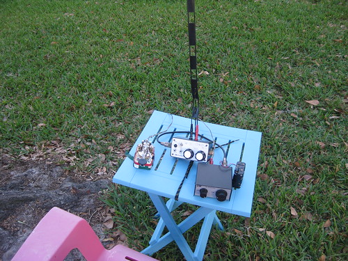
So with that in mind, let's get our minds on the gutters.

Notice, I said, on the gutters, not in the gutter.

Gutters, if they are made of metal, can carry RF, and they can do it reasonably well, if some things are kept in mind. They basically function as a random length wire antenna, although if you have the space for it, and do a little planning and experimentation, you could possibly create a system resonant on a particular frequency. Here are the rules about using METAL gutters as antennas:

1. ELECTRICALLY connect the pieces. Most gutter pieces are either friction fitted, or connected together via a small screw. This is a mechanical connection, and is not good enough for RF. RF needs to see the pieces as one piece electrically, so there needs to be a low resistance connection between the pieces. As it stands, they are loosely electrically connected joints, and can actually act as product detectors, meaning they they are small bits of radios themselves! This results in all kinds of noise and interference on your received signal. Fortunately this is easy to fix, but it does take work. This is also good information for you to store away when you want to install a mobile radio, as you will want to electrically connect the various body panels on your vehicle.

To connect gutter pieces you will need:

  • self tapping screws (many)
  • A machine screw
  • 2 washers (for machine screw)
  • locking nut (for machine screw)
  • sandpaper
  • copper bearing conductive grease.
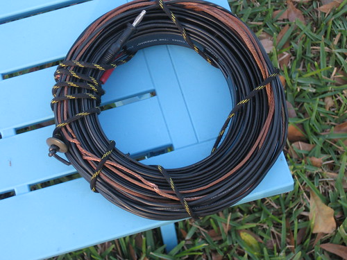
  • A coax pigtail, one end with an SO-239 connector, the other should have the braid and center conductor seperated for about 6-10 inches.
  • ohm meter
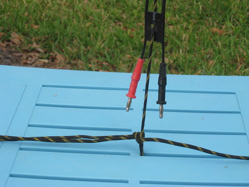
Sand down the contacting surfaces for each section of gutter or downspot. Make sure you can fit them together tightly, but before you do, put some conducting grease between the contacting surfaces. Secure the pieces together with at least two self tapping screws. Check the electrical continuity between the two sections of gutter/downspout with an ohm meter. There will probably be some resistance, but there shouldn't be much, and if things are wiggled a little bit, the resistance shouldn't jump around. The machine screw, washers and nut is for the feedpoint. I've always fed gutter antennas from the bottom of a downspout using a coax pigtail, one end with an SO-239 UHF connector (Same as what's on the back of most HAM/CB radios) , center of the coax going to the gutter, and braid going to a nearby grounding point of some kind, either a ground rod (worst case scenario), Radials (better), or groundrod with radials (Best option!). Sand the area, outside and inside, where you want to feed the antenna, making sure you remove all the paint on an area a little bigger than your washer. Put one washer on the inside of the downspout with the nut, and one on the outside between the screw head and the downspout. Before you snug everything up, wrap your feedline center conductor around the screw a couple of times between the washer and the downspout. Give the washers, screw, and downspout a litte conductive grease, and tighten everything up.

  
2. Create a good ground plane. Unless you live near the ocean, your ground plane stinks. Shooting a ground rod into the ground near the spout where you will be feeding your antenna is one thing you can do. It will at least help give you some lightening safety. Hooking some radials up to that rod would be even better. Hook up at least 4, and space them an equidistance apart out in the front. Make sure they are at least a quarter-wavelength long on your lowest frequency of operation. Because that can be 66' for frequencies in the 3.5 MHz range, you may need to get creative on where they go, and how they sprawl out. I use a hand operated sidewalk edger to make a small slit in the ground, that can be used to bury the ground radial. You'll need to find some similar way of hiding the radials. When you connect the ground braid from the coax pigtail to the ground system of the antenna, use some more of the conductive grease.

  
3. Did you use the conductive grease? If not go back and use it! Water makes copper corrode quicker, and copper braid readily absorbs water. Corroded copper does not conduct RF well. Because gutters are designed to carry water, it's important to try and make the connections as waterproof as possible. The conductive grease helps do that, and it helps make the electrical connection better. USING REGULAR GREASE IS NOT RECOMMENDED! regular grease will act as an electrical insulator. That's the opposite of what we want to do.

4. Run as short a line as possible from the antenna's pigtail to an antenna matching device. You may or maynot need a balun. The antenna matching device should be grounded to the same point as the antenna, although if you can't do that, don't worry. Just get it grounded.

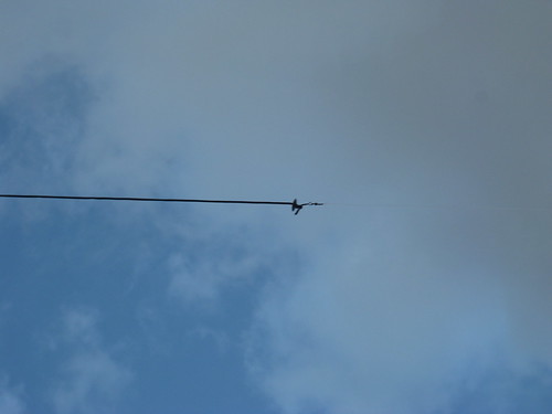
That's how you make a gutter system into an antenna. At my buddy's apartment, we stealthily connected the pieces of a downspout together electrically, and it wasn't easy. Fortunately, the downspout could be accessed from a stairwell. He had a great time on HF with 100 watts and less, but had a better time with a stealth longwire. That's for another post though...


EDIT:  Links for other downspout antennas will go here as people get them to me!
WB3GCK's antenna

Saturday, May 14, 2011

My Favorite Cheap HF Antenna, The W3EDP

station
The station, my "Killer Watt" SW-40, Emtech ZM-2 Tuner, and W3EDP antenna, ready to play!

There's a good bit of info on the interwebs about the W3EDP:


Here's what it looks like (kinda) - but the info's a little off.
Here's some good info, but no pictures
A slew of experiences from a popular ham radio forum
Another Blog article, looks like he may have done some modeling of the antenna too!
I call mine the improved W3EDP because of some theory that I learned about end fed antennas in general, and about the W3EDP in particular.

Some time ago, on QRP-L, there was a great post about the W3EDP By W6JJZ
It was epic in my understanding, especially this part:
To understand the W3EDP, instead conceive of the short side as
one side of a feedline that's been separated or pulled apart from
the other side of the feedline.

Now in your mind move the short side so that it's parallel to the
first 17 feet of the long side and anywhere from several inches
to a foot or so away. What you have is a section of feedline.

I added the emphasis.
A W3EDP is an end-fed zep! Well, I guess you should say that a classic W3EDP is a pragmatic zep, because the matching section of line goes wherever you want, as a mislabeled "counterpoise."
To improve the design, I made a W3EDP antenna in Zepp formation. I took some 450 ohm ladder line (Wireman #553) and used it for the first part of the 85' wire, and all of the 17' wire, adjusting for velocity factor. Then I took 68' (85-17) of "Silky" antenna wire (Wireman #523) and attached it to one side of the ladder line. I put a red banana plug on the 'long' side, and a black one on the 'short' side.

closeup
The banana plugs, notice that I've added some string through the solid parts of the insulation for stress relief.

I used buttons for insulators.
far_end
you can see the button on the end, it's from old army surplus pants. They make the best insulators because they are durable, unobtrusively colored, and suitable for modification (you can make the holes bigger with a pocket knife)

When rolled up, the antenna is compact and easy to store
W3EDP_ready
Ready to store.

boxedup
in the box!
It goes anywhere!

That's my account of this wonderful antenna, I hope you can build one. I've used this one to talk to people all over the place. The silky wire means it bends well without kinking, you can also get good result with speakerwire, but using speakerwire means you will have to tear the wires apart. You could just make two at once, and give one to a friend!

HV FN ES 73!